Denso 4 Pin Relay Diagram
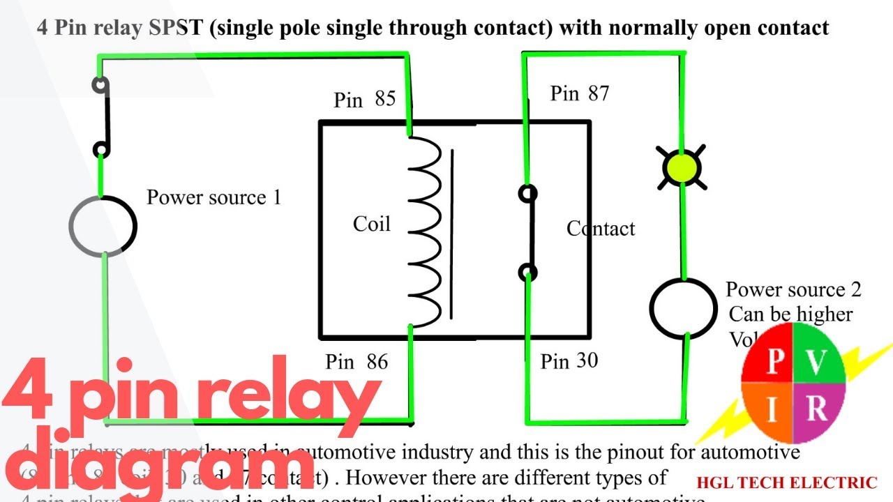
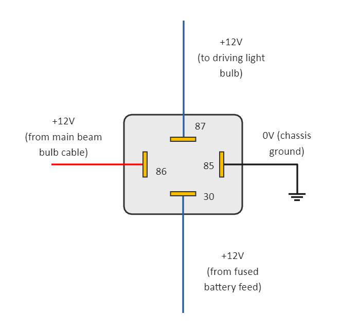
4-Pin Relay A standard 4-pin relay has four connections: two for the control circuit (85, 86) and two for the high-power circuit (30, 87). Here's a simple way to wire a 4-pin relay: Pin 30 - Connect this pin to the power source. This is the power that will be used by the relay to switch the device on.
Automotive Relay Wiring Diagram
4-Pin-Relay-Wiring-Diagram Installing a relay is not a hard task provided that you know the schematics of the relay. Before installing the relay, you should understand the wiring diagram of the relay. First, we will explain the four and five-pin relay wiring diagram so that you have a good understanding of the relay diagram.

Understanding The 4 Pin Relay Wiring Diagram WIREGRAM
To wire a 4-pin relay, you need to connect the common pin to the power source, the normally open pin to the device you want to control, and the normally closed pin to the ground or earth. The control pin is connected to a switch or a control module that activates the relay.

Bosch 4 Pin Relay Wiring Diagram
Common terminal: This terminal is connected to either the NO or NC terminal, depending on the state of the relay, as explained above. 4 Pin Relay Wiring Diagram. A commonly used 4 Pin relay configuration for an Automotive relay is shown by a make-or-break circuit: Make-or-Break circuit: This type of circuit can be found in bikes and cars.

Relay Wiring Diagram 4 Pin Diagram Wiring Diagram For 4 Pin 30 Amp 12 Volt Full Version Hd
What is a 4-Pin Relay? A 4-pin relay is an electromechanical switch that controls the flow of current between two circuits. It consists of four terminals: two coil terminals and two switch terminals. The coil is energized when a small current flows through it, activating the switch to allow a larger current to flow in the main circuit.

Diagram For Wiring A Relay
4-Pin Relays Relay Wiring Diagram What is a Relay? As mentioned earlier, a relay is essentially a switch. Unlike a traditional switch, which we flip or toggle to make it ON and OFF, a relay is an electromechanical switch. The 'mechanical' action of moving the switch between ON and OFF positions is achieved by an 'electrical' signal.
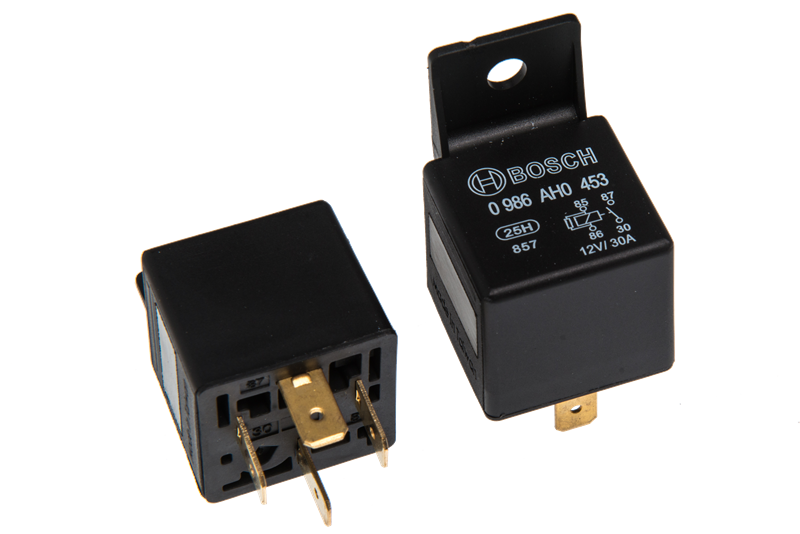
Bosch 4 Pin Relay Spitronics Engine Management Systems
59.1K subscribers Subscribe Subscribed 179K views 3 years ago Quick and easy way to wire a relay to safely power added lights. Why you need a relay is also covered. This video will explain.

OEM GM 4Pin Relays (2 Pack) 13422668 High Power 4Terminal MultiUse Relays Automotive
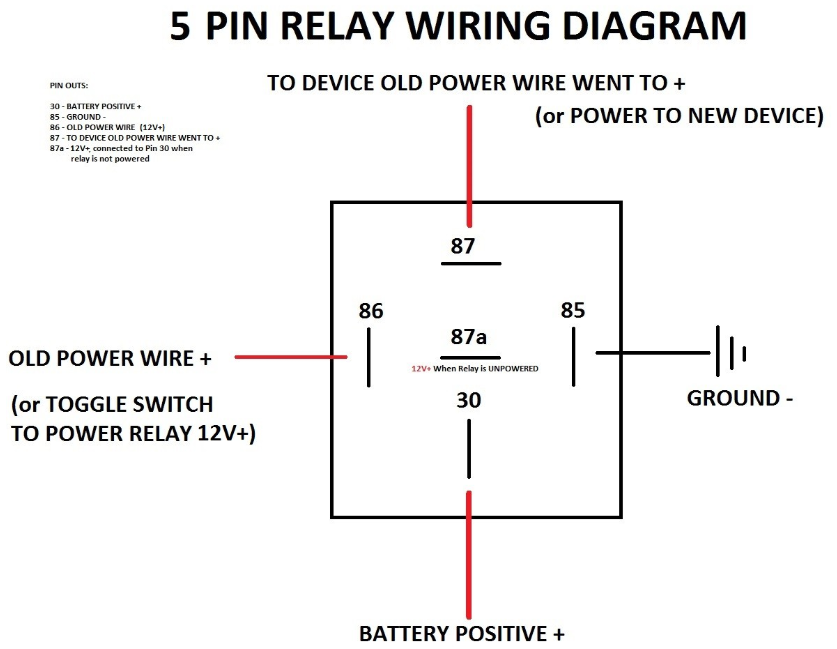
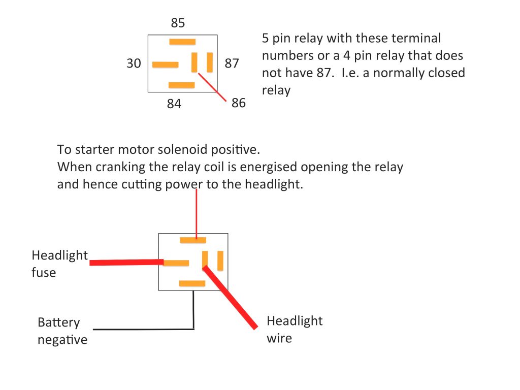
According to DIN 72552 Standard, each pin of a relay is numbered 85, 86, 30, 87, and 87a. You need to know that a relay has two circuits, a coil circuit (also called a "low current circuit", or "inductive circuit"), and a high-amperage circuit.

Understanding The 4 Pin Relay Wiring Diagram For A Horn WIREGRAM
Looking for Pin Relays? We have almost everything on eBay. No matter what you love, you'll find it here. Search Pin Relays and more.

Relay Wiring Diagram 4 Pin
A 4 pin indicator relay is considered to be an electrical protective device which is mainly used in industrial settings. It is designed to monitor and control the flow of electricity by providing visual indications when something is wrong with the circuit. Such as a short circuit, an overload, or over/under voltage conditions.

12v 30a Relay 4 Pin Wiring Diagram Wiring Draw And Schematic
how to wire a 4 pin relay.Equipment used in the filming is Gopro Hero 8 fromhttp://Gopro.comOthe equipment used for filming is the iSteady gimble fromhttp://.
4 Pin Relay Wiring Diagram Cadician's Blog
Wiring 4 Pin Relay: A Comprehensive Guide. A 4-pin relay is a commonly used electrical component that allows you to control a high-current circuit using a low-current signal. It is widely used in automotive applications such as controlling lights, horns, and motors. Understanding how to properly wire a 4-pin relay is essential for anyone.

10+ 4 Pin Relay Wiring Diagram Robhosking Diagram
A 4 pin relay is a commonly used type of relay, with four pins for easy wiring and installation. To properly wire a 4 pin relay with a switch, you will need to connect the following pins: Pin 30: This is the common pin, which is usually connected to the power source. Pin 87: This is the normally open (NO) pin, which is connected to the load.

2 x Car Relay Automotive Relay 12V 40A 4 Pin Wire with 5 outlets NEWin Terminals from Home
1. Identify the wires of Headlights: The first step in order to wire the relay for the driving light is to identify the wires coming out of the driving lights. Normally, there are two wires connected to these lights out of which, one is the power wire, normally having a red color, and another one will be ground wire black in color. 2.
4 Pin Relay Diagram EdrawMax EdrawMax Templates
In this article, we'll explain the basics of reading a wiring diagram for a 4 pin relay. First, let's look at the pins on a 4 pin relay. A 4 pin relay is typically made up of four pins: a power source pin, a ground pin, a signal pin, and a control pin. The power source pin connects to the power supply, while the ground pin connects to the.
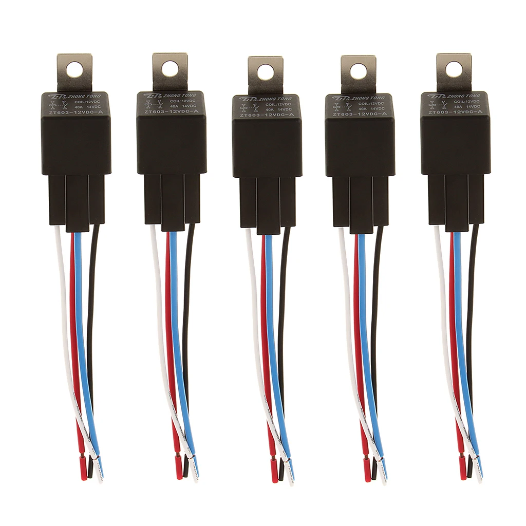
5x 12V Relay 4 Pin With Socket Base/Wires/fuse Included 40Amp SPSTCar Switches & Relays
Learn how to wire a standard 4-pin automotive or powersports relay in this quick video.